STEEL STRUCTURES
Steel is used for almost every type of structures, including industrial buildings, infrastructure, bridges, high-rise buildings, towers, etc. AXISVM provides a complete solution for the analysis and design of steel and other metal structures, including strength and stability verifications, fire design of members, and design of welded and bolted connections. Critical load multipliers and buckling shapes can be obtained from a buckling analysis for frame, truss, and shell structures. AXISVM also supports finding the optimal design solutions.
Detailed design report sample for a pedestrian bridge (compressed chord buckling) >>
SD1 MODULE
Design of steel members
SD8 MODULE
Fire design of steel members
SD9 MODULE
Cross-section optimizaton of steel members
SC1 MODULE
Design of steel members
7DOF MODULE
Beam elements with 7 degrees of freedom
SD1 MODULE
The SD1 module performs the design and verification of steel structural members in ultimate (ULS) and serviceability (SLS) limit states. Flexural buckling, lateral torsional buckling, web shear buckling, and strength verifications considering axial forces, bending moments, shear forces, and their interaction are included. Both elastic and plastic design methods are allowed, depending on the cross-section classification. The class of the cross-section, buckling length (FB), and critical bending moment (LTB) can be determined automatically or can be specified by the user. The software verifies the deflections of beams and the sway of columns in SLS load combinations. Detailed documentation of the design calculations can be created.
Documentation sample (Steel member design) >>
Requirements / recommendations
- no requirement
DESIGN CODES
Eurocode3
EN 1993-1-1
Swiss standard
SIA 263
Italian standard
NTC
CHARACTERISTICS
- automatic classification of the cross-section considering the internal forces
- design of members with class 4 cross-section
- automatic determination of critical axial force and critical bending moment
- detailed documentation of the design calculations
CROSS-SECTIONS
rolled I profiles
welded I profiles
hollow rectangular profiles
circular profiles
single symmetric I profiles
T profiles
solid rectangular and circular profiles
! limited support for custom/arbitrary profiles
DETAILS
DESIGN MEMBERS

In AxisVM the design members consist of a selection of finite elements that have the same material and local coordinate system orientation.
FLEXURAL BUCKLING
The critical axial force / buckling length of the design members can be calculated automatically. The so-called AutoNcr method determines buckling length based on the geometry and the distribution of internal forces in the model. The buckling length of each design member is computed considering the stiffenning effect of the connecting members. This method is based on the rules recommended by the European Convention for Constructional Steelwork (ECCS TC8: Rules for Member Stability in EN 1993-1-1: Background documentation and design guidelines).
LATERAL TORSIONAL BUCKLING
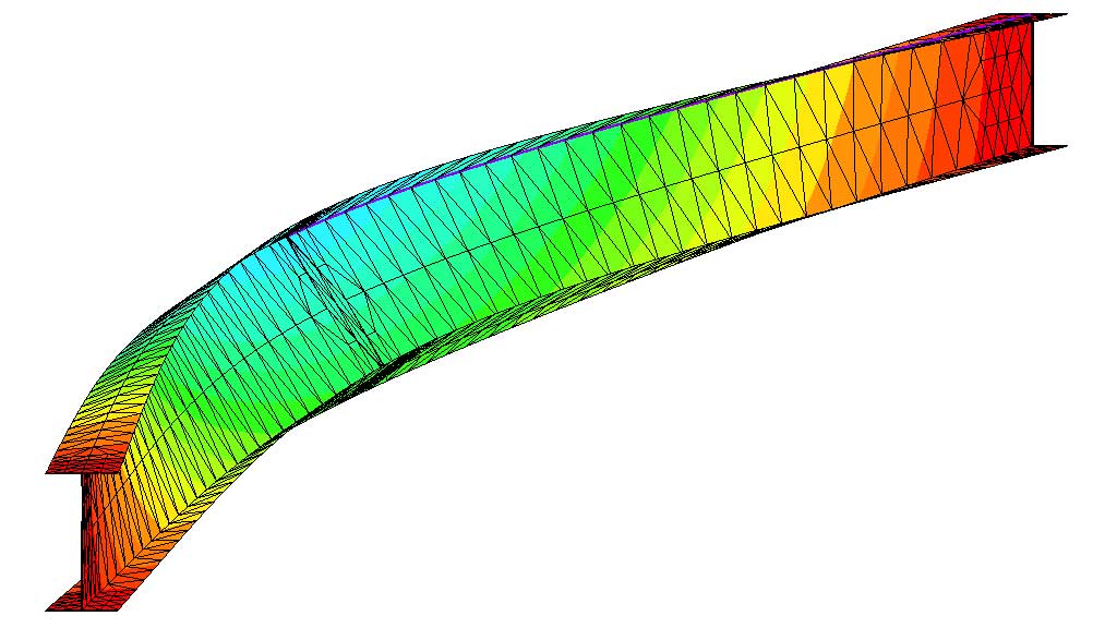
The critical bending moment can be calculated by a formula or automatically by AxisVM. This method creates a finite element sub-model for each design member and using which it determines the Mcr for each load combination. This method handles variable cross-sections and cantilevers as well. The finite element sub-model of a beam contains at least 30 finite elements in which each node has four degrees of freedom that are essential for the lateral torsional buckling. This method builds the beam stiffness considering two components: the first one is linear, the second one has geometric nonlinearity.
DESIGN CALCULATIONS
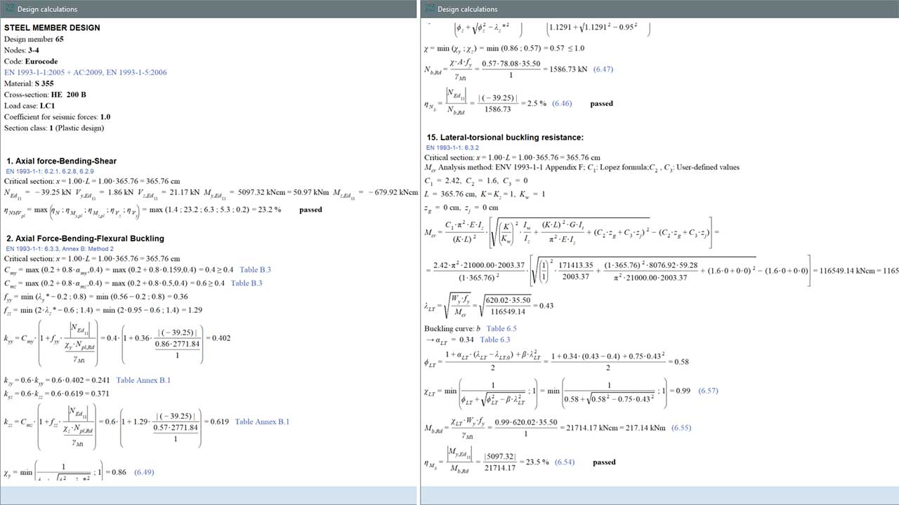
Detailed documentation of the design calculations can be generated and attached to the report by one simple click.
SD8 MODULE
Fire design of steel members is available in SD8 module. The design calculation considers the reduction in strength and stiffness of steel material on elevated temperature that makes steel structures very sensitive for stability failure in fire. Critical temperature that is one of the essential parameters by the selection of intumescent coating thickness is also an outcome of the design calculation. The fire effect is given by standardized prescriptive, parametric or user-defined fire curve (considering simulation or fire test results). Steel temperature is calculated automatically by closed formula or by the solution of two-dimensional heat conduction problem. The calculation of steel temperature considers the effect of passive fire protection material on the element.
Documentation sample (Steel member design for fire safety) >>
Requirements / recommendations
- fire design of steel members is based on the steel member design, thus SD1 module is a prerequisite to the use of the SD8 module
DESIGN CODES
Eurocode1
EN 1993-1-1
Eurocode3
EN 1993-1-1
EN 1993-1-2
Italian standard
SIA 261
SIA 263
Swiss standard
NTC
CHARACTERISTICS
- automatic calculation of steel temperature using a standard, parametric, or userdefined fire curve
- design of members with class 4 cross-section
- stability parameters for fire design
- calculation of critical temperature
- detailed documentation of the design calculations
DETAILS
USER-DEFINED FIRE CURVE
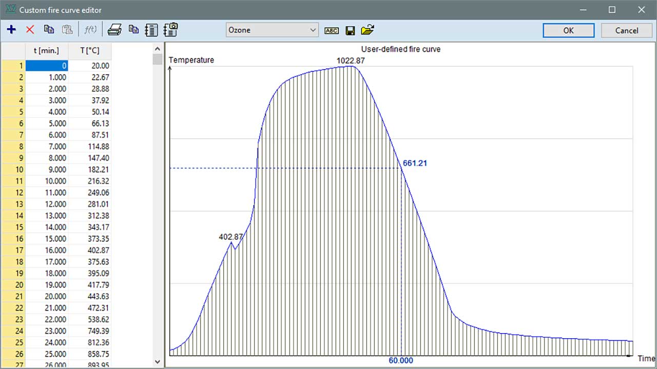
To define the fire effect user-defined fire curves are accepted, besides standardized prescriptive and parametric fire curves, therefore AxisVM allows to perform fire design based on simulation or fire test results.
TEMPERATURE DISTRIBUTION
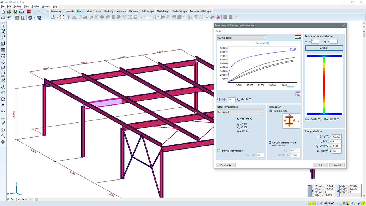
Steel temperature is generally determined via closed formula from the design code however, for I and rectangular hollow sections a more accurate temperature distribution may be used. Temperatures within the cross-section are calculated by the finite difference method. In this case, a two-dimensional heat conduction problem is solved. The analysis considers the temperature-dependent thermal conductivity of the steel material.
CRITICAL TEMPERATURE
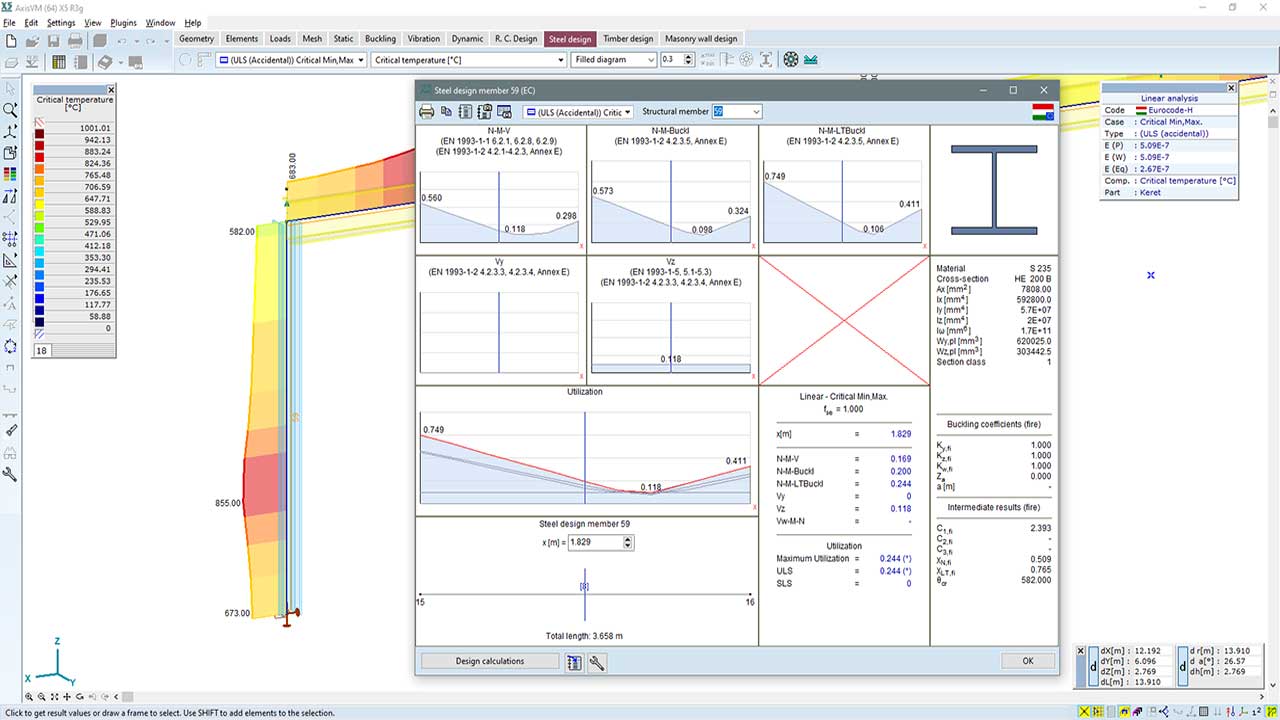
In many cases, the critical temperature (steel temperature where failure of the element occurs) also has to be determined. For example, the thickness of intumescent coating fire protection is selected on the basis of section factor (A/V) and critical temperature. AxisVM determines the critical temperature along the design member, which can lead to a more economical and cost-effective design.
SD9 MODULE
Cross-section optimization of steel structures makes previously defined and designed steel design members more efficient by fine-tuning the cross-section dimensions and reducing the self-weight. The optimization uses the steel design parameters previously assigned to the design members and it can also be performed with the consideration of fire design rules for load combinations that contain fire load case. The objective of optimization can be minimum weight, minimum height or minimum width. AxisVM uses the so-called Particle Swarm Optimization (PSO), a stochastic computational method for finding optimum.
Requirements / recommendations
the SD9 module uses the steel design parameters previously assigned to the design members within the SD1 and SD8 modules, thus at least the SD1 module is a prerequisite to the use of the SD9 module
DESIGN CODES
The SD9 module is independent from standards.
CHARACTERISTICS
- the objective of optimization can be minimum weight, minimum height, or minimum width
- a heuristic search algorithm Particle Swarm Optimization (PSO) is invoked to find the optimum
- optimization with the consideration of fire design rules
CROSS-SECTIONS
- I profiles
- single symmetric I profiles
- rectangular and circular hollow profiles
- T profile
- C profile
- 2U profiles
! Variable cross-sections cannot be optimized
DETAILS
OPTIMIZATION ALGORITHM
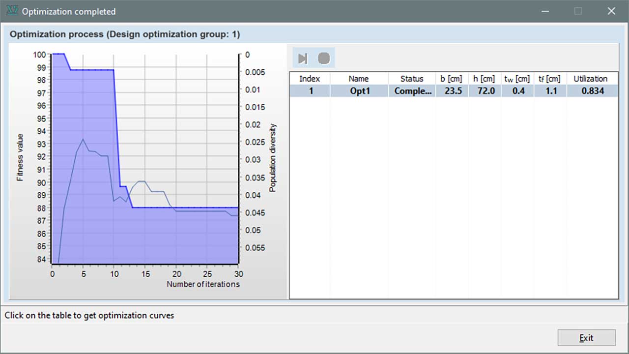
Particle Swarm Optimization (PSO) is an evolutionary algorithm developed in the 1990s. The PSO process runs for a given number of iterations, and due to its stochastic nature, it can find multiple local optimums. The number of iterations is determined by the program trying to balance running time and the fullest possible mapping of the search-space. Moreover, if the algorithm finds no changes in the results after a long period, it assumes that it detected the global optimum. In multi-threaded mode, the search space is partitioned among the threads.
OPTIMIZATION RESULTS
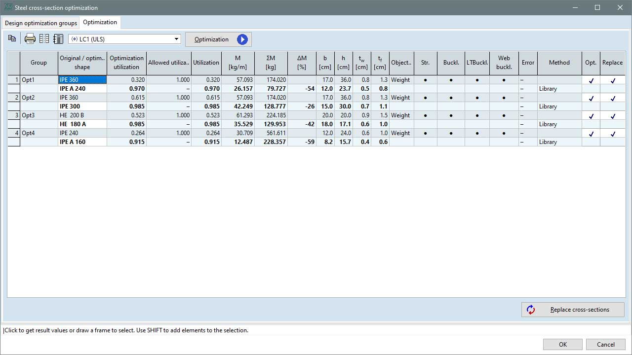
Optimization results with original and optimized cross-sections, utilizations, and other details are summarized in a result table. The cross-section of the element can be replaced by one click.
SC1 MODULE
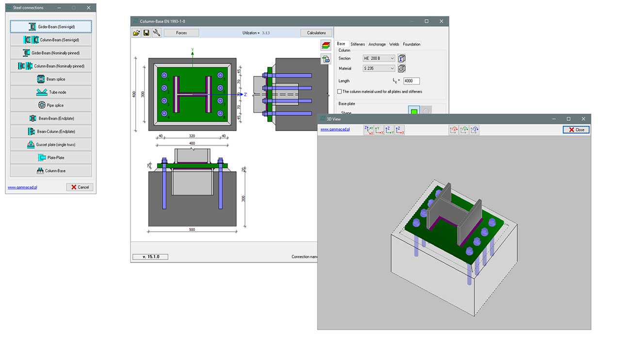
Design and verification of welded and bolted steel connections can be performed with the SC1 module. Altogether, eleven connection types are supported. The so-called component method is applied that means that the resistance of the connection is determined on the basis of the resistances of its basic components. 3D rendered view and detailed documentation with view and section drawings can be generated.
Documentation sample (Beam – column front plate joint ) >>
Learn more: SC1 API User’s Manual >>
Requirements / recommendations
- no requirement
DESIGN CODES
Eurocode3
EN 1993-1-1
EN 1993-1-8
CHARACTERISTICS
- flexible and user-friendly definition of design parameters
- 3D view of the connection
- design of welded and bolted connections
- detailed documentation of design calculations
CONNECTION TYPES
column – beam (semi-rigid)
column – beam (nominally pinned)
girder – beam (semi-rigid)
girder – Beam (nominally pinned)
beam – beam (end-plate)
beam – column (end-plate)
beam splice
column base
pipe splice
gusset plate (single truss)
tube node
DETAILS
STANDALONE STEEL CONNECTION
Standalone steel connection plugin is available in the SC1 module. Neither nodes nor members need to be selected. The cross-sections can be specified by selection from cross-section library or from a list that contains previously defined cross-sections in the model.
DETAILED DESIGN CALCULATION
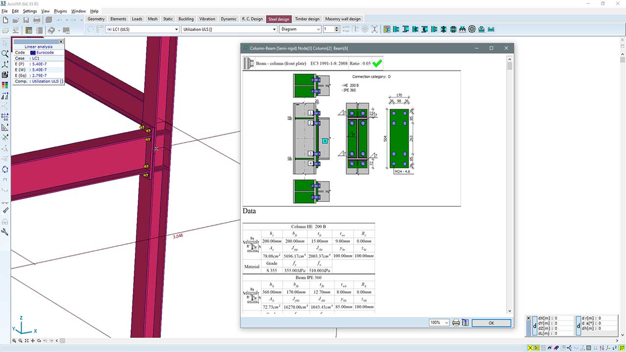
Detailed documentation of the design calculations can be generated and attached to the report by one simple click. The documentation includes: 1) view and section drawings of the connection and dimension lines; 2) geometric and material properties of the components; 3) internal forces and moments at the node; 4) design results. The utilization results are colour-mapped. Green colour means it passed, and the red means it did not pass.
7DOF MODULE
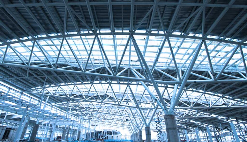
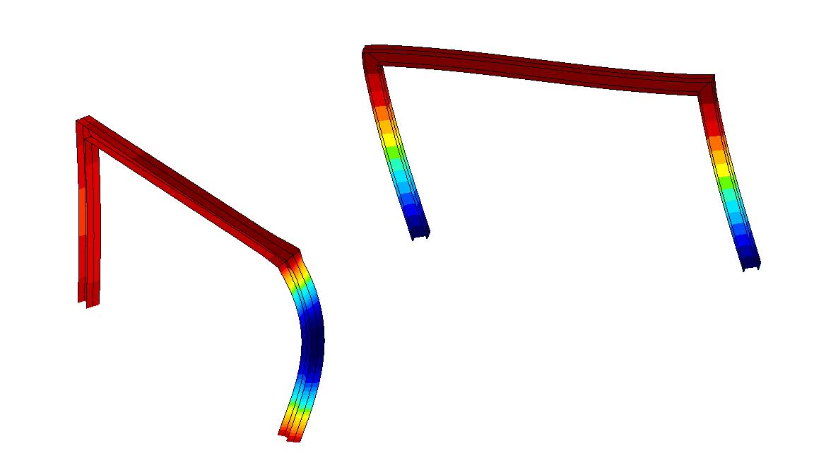
This module provides the option to define beams with 7 degrees of freedom. The additional, 7th DOF represents the warping of the cross-section.
A circular cross-section of a bar, or a circular hollow section will remain in-plane as a result of uniform twisting, however, all other section types will experience warping of the cross-section.
Warping occurs when the twisting of a member results in the cross-sections distorting out-of-plane along the direction of the members longitudinal axis. If the out-of-plane distortion is restrained or prevented, longitudinal stresses and strains develop in the member. Warping can be constrained by a support or concentrated torque.
Constrained warping can significantly affect the stress distribution in thin-walled beams and columns, which should be considered in the design. Warping is also important if the members of the structure are sensitive to lateral-torsional buckling.
Requirements / recommendations
7DOF is an add-on module to the basic packages (analysis options), and is recommended when designing beam structures with a tendency to warp
DESIGN CODES
The 7DOF module is design code independent
CHARACTERISTICS
- an element type to be used for modeling thin-walled steel structures
- the so-called warping transmission is based on Basaglia et al. [1]. Since the 7th degree of freedom is assigned to the beam elements, the degree of freedom of different beam elements connected to a node is not always the same. The warping transmission depends on the structural design of the nodes, which can be specified in the program by a transmission multiplier
- in the case of a nonlinearly elastic or plastic material model, the software considers the additional stresses due to the inhibited warping
[1] C. Basaglia, D. Camotim, N Silvestre. Torsion warping transmission at thin-walled frame joints: Kinematics, modelling and structural response, Journal of Constructional Steel Research (69), 2012
DETAILS
DEFINITION OF A 7DOF BEAM ELEMENT
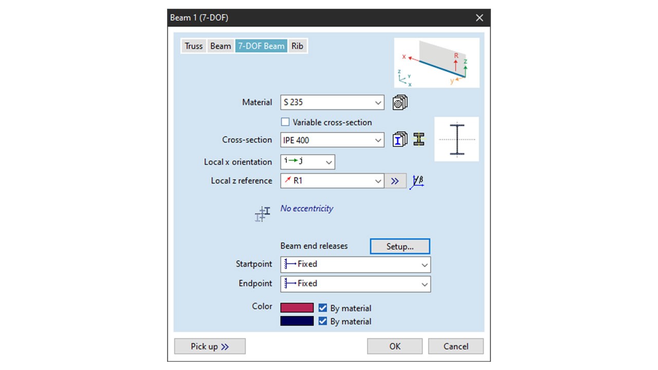
7 degrees of freedom beam elements can be selected on the Line elements dialogue window.
DETAILED DESIGN CALCULATION
The diagonal joint type provides complete-direct, the box type provides complete-inverse, and the box-diagonal joint type provides fixed warping transmission.
Transmission parameter can be set in the Spring characteristics dialogue window.
SETTING WARPING TRANSMISSION PARAMETERS USING END RELEASES
Warping DOF end-releases can be set in the Beam end releases dialogue window. Depending on the design of the connection, the available options are fixed, free, or semi-rigid.